Raspberry Pi to Arduino SPI Max Data Transfer Rate
There are many ways to send data from Raspberry Pi to an Arduino. One of these is by using the SPI interface. Here are some of the things to consider when trying to get as much speed as possible for the transfer. The end goal of this project is to control addressable led strips from the arduino so we need to transfer as many bytes as possible from the pi to the arduino in the highest transfer rate possible.
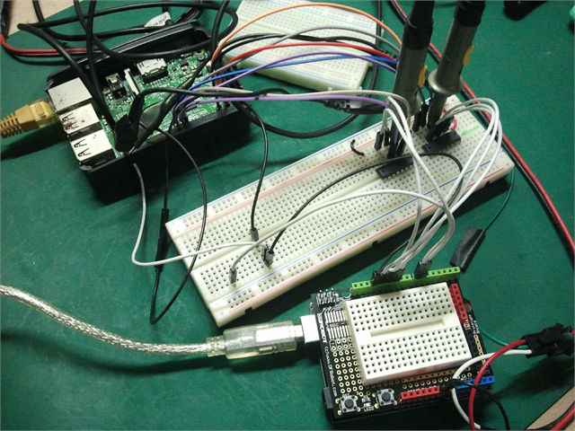
The setup I’m using is shown above.
Theory
The specs of the raspberry pi give it a very high SPI transfer rate – in the tens of megabits per second. The limiting factor is the arduino where the receive rate is Clock speed / 4. So if you’re using a 16Mhz arduino, the theoretical rate at which it can receive is 4 Mbits per second or 500 KBps. Unfortunately, depending on your practical considerations, you will most likely not get this high rate.
Hardware: Signal rise time
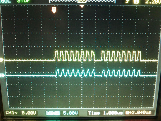
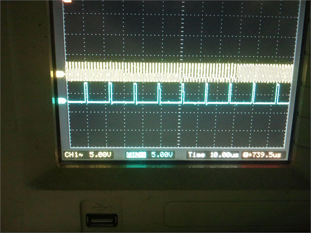
In the image above, the yellow lines are from the raspberry pi gpio output going to the level converter and the blue lines are from the output of the level converter. We’re running the SPI at 4Mhz. The output from the PI looks ok but the input going to the Arduino don’t look like proper square waves anymore.
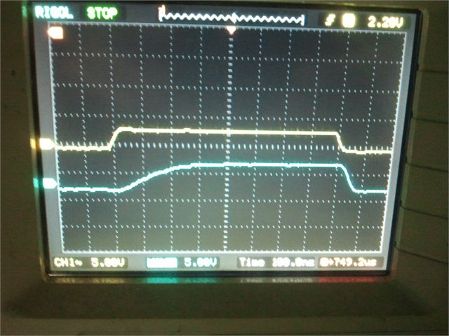
The raspberry pi gpio’s have 3.3 v outputs while the arduino inputs are 5 volts. I’m using a CD4050 IC to convert the voltage level. The output takes around 400 nanoseconds to get to 5 volts. This delay caused by the level conversion means the maximum clock cycle is 800 nano seconds limiting you maximum speed to 1.2 5Mbps (We set the PI at 1Mhz). Some other level converter chips may have faster rise times. A common one is the 74LVC245 but I haven’t tried it yet.
Software: From Wiring pi library to interrupts in Arduino 1 byte transfers at 1 Mhz
I’m using the wiring Pi library to send data through the SPI interface. On the arduino side, we use an interrupt handler to get the data sent by the pi. The Arduino sends back a reply to the PI.
Here’s the code snippet on the PI side. We send 2 times because the way SPI works is that it sends the return byte from the arduino at the same time as the next send of the PI.
int ping(int fd)
{
   unsigned char b,bAck;
   b = MYSPI_PING;
   wiringPiSPIDataRW2(fd,SPI_CHANNEL, &b,1);
   b = 0;
   wiringPiSPIDataRW2(fd,SPI_CHANNEL, &b,1);
   bAck = b;
   if (bAck == MYSPI_ACK) {
      return(0);
   } else {
      printf("bAck = %02x  ",bAck);
   }
}
On the Arduino side we have the interrupt handler. If it receives the ping byte it just responds with an ack byte. The two asm() lines trigger an output pin on the ardunio to go high and low so that we can see when the interrupt code gets called on the oscilloscope display.
ISR(SPI_STC_vect)
{
   byte c;
   asm ("sbi %0, %1 \n" : : "I" (_SFR_IO_ADDR(PORTD)), "I" (PORTD6));
   c = SPDR;
   if (c == MYSPI_PING) {
      SPDR = MYSPI_ACK;
   }
   asm ("cbi %0, %1 \n" : : "I" (_SFR_IO_ADDR(PORTD)), "I" (PORTD6));
}
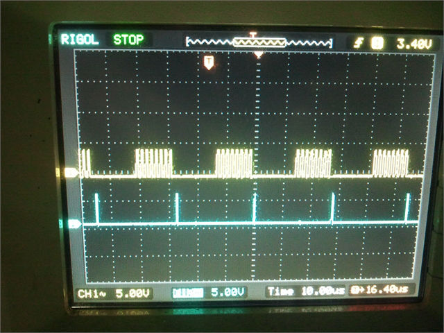
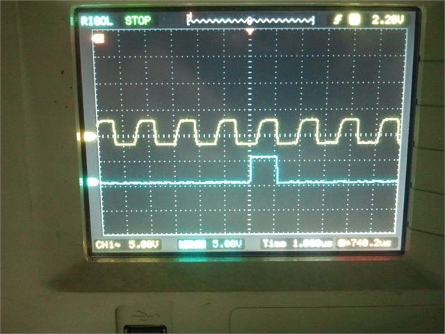
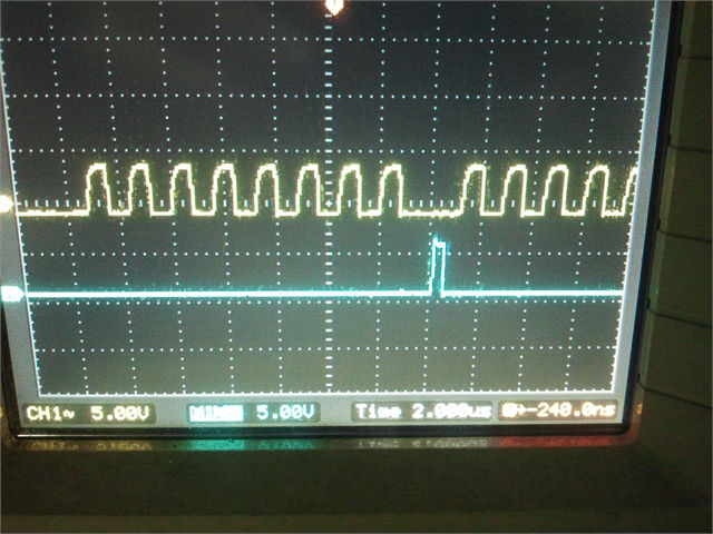
In the image above the yellow lines are the clock signal from the raspberry pi while the blue lines represent the interrupt received by the arduino. The SPI on the PI is set to transmit at 1 Mhz, 1.e. 1 micro sec per bit but the rate seems more like 1 bit per 1.25 microsecs based on the oscilloscope. Each byte is sent approximately every 15 microseconds. The 10+ microsecond gap seems to be coming from the SPI device driver on the PI. Using this method we can get a maximum of around 60KBps transfer rate.
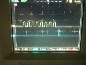
In this closeup we can see the interrupt in the Arduino taking up less than a microsecond, but this is just the code block itself. There is still additional overhead from the triggering and processing of the interrupt.
Software: From Wiring pi library to interrupts in Arduino Multiple byte transfers
If we could reduce the gap between byte transfers we could get a higher transfer rate. Here’s what happens when we try a 2 byte transfer. This would use the following code from the PI.
int ping(int fd)
{
   unsigned char b[2],bAck;
   b[0] = MYSPI_PING;
   b[1] = 0;
   wiringPiSPIDataRW2(fd,SPI_CHANNEL, b,2);
   bAck = b[1];
   if (bAck == MYSPI_ACK) {
      return(0);
   } else {
      printf("Error bAck = %02x\n",bAck);
      return(-1);
   }
}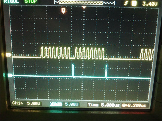
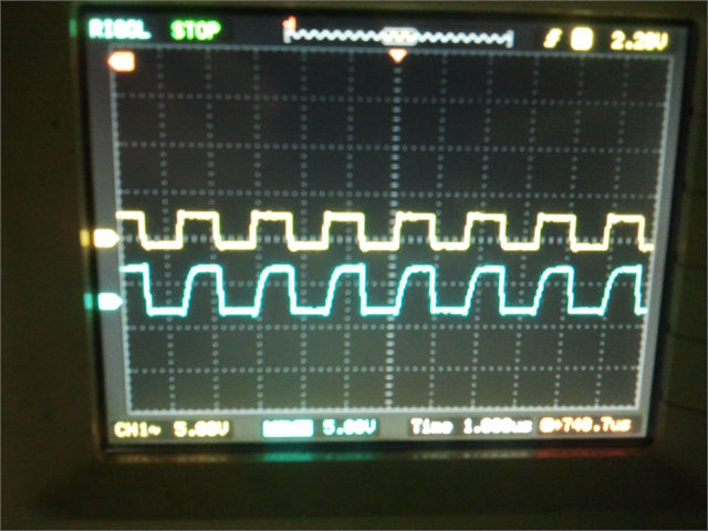
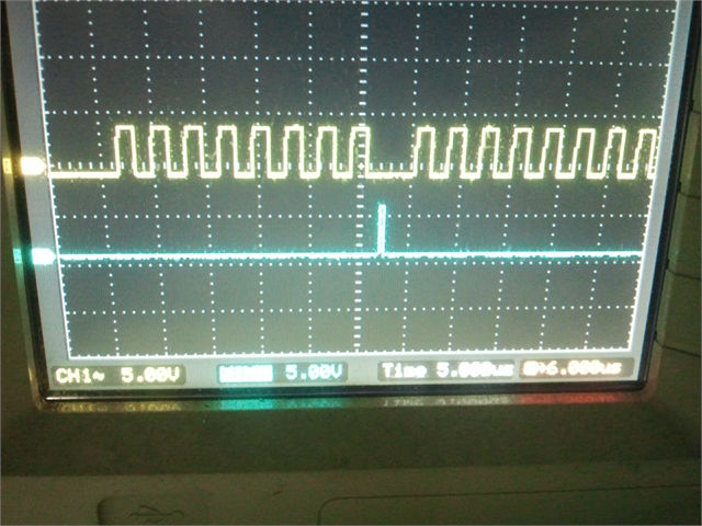
The image above shows the transfer at 1 Mhz. The two bytes are send more closely together but you can still notice the gap between function calls caused by the device driver. The problem is that the time for interrupt handling on the Arduino is shortened. The following are the results:
Error bAck = ff Fail header ack 110823 789 0
Error bAck = ff Fail header ack 110934 790 0
Error bAck = ff Fail header ack 111121 791 0
Error bAck = ff Fail header ack 111381 792 0
This says that the response sent by the Arduino is wrong for about every 1000+ bytes.
You can see in the closeup that the end of the interrupt is very close to the start of receiving the next byte. This may be the cause of the errors. Depending on the app we could live with this by doing retransmits on errors but we’re transferring big blocks quickly for a LED strip where we need every byte to be accurate.
Software: From Wiring pi library to interrupts in Arduino 1 byte transfers at 500 khz
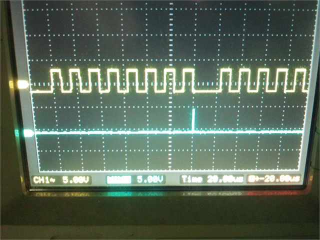
So we now try it at half the rate – 500 khz.
In the two images above you can see that there’s a bigger gap between the end of the interrupt processing and the start of the next byte. Here are the results.
Error bAck = ff Fail header ack 101757 276 0
Error bAck = ff Fail header ack 101873 277 0
Error bAck = ff Fail header ack 102419 278 0
Error bAck = ff Fail header ack 103523 279 0
There are still errors, althoug it’s only about a third of the errors at 1 Mhz.
Software: From Wiring pi library to interrupts in Arduino 1 byte transfers at 100 khz
At 100 Khz, there are no errors, but this just gives a transfer rate of around 6 KBps.
Software: Not using interrupts
In this final test, we try sending 100 bytes straight from the PI to the Arduino at 1 Mhz. The code on the PI end is:
len = 100;

wiringPiSPIDataRW2(fd,SPI_CHANNEL,buff,len);
And on the Arduino side, to avoid the overhead of interrupts, we just keep waiting in a tight loop. We just included some dummy code to represent buffer leng checks and timeouts.
while (1) {
   while (!(SPSR & (1<<SPIF)));
   asm ( "sbi %0, %1 \n"  : : "I" (_SFR_IO_ADDR(PORTD)), "I" (PORTD6));
   timeOutCtr = 0;
   SPDR = 0x51;
   buffLen++;
   if (buffLen >= bytesToRecv) {
      state = 0;
   }
   asm (  "cbi %0, %1 \n"  : : "I" (_SFR_IO_ADDR(PORTD)), "I" (PORTD6));
}
At 1 Mhz, the output still has errors. This is the returned byte stream from the Arduino. They should all be 0×51. There are still a lot of errors as you can see.
51 51 28 d1 51 51 51 51 28 d1 51 51 51 51 28 8f 51 51 28 d1 51 51 51 51 28 d1 51 51 51 51 28 d1 51 51 51 51 28 d1 51 51 51 51 28 d1 51 51 51 28 a8 d1 51 51 51 28 d1 51 51 51 51 28 d1 51 51 51 51 28 d1 51 51 51 51 28 d1 51 51 51 51 28 d1 51 51 51 28 d1 51 51 51 51 28 d1 51 51 51 51 28 df 51 51
At 100 khz it worked so the transfer rate is around 12.5 KBps.
51 51 51 51 51 51 51 51 51 51 51 51 51 51 51 51 51 51 51 51 51 51 51 51 51 51 51 51 51 51 51 51 51 51 51 51 51 51 51 51 51 51 51 51 51 51 51 51 51 51 51 51 51 51 51 51 51 51 51 51 51 51 51 51 51 51 51 51 51 51 51 51 51 51 51 51 51 51 51 51 51 51 51 51 51 51 51 51 51 51 51 51 51 51 51 51 51 51
So there you have it, because of a mixture of hardware and software issues the transfer rates you will get may note reach the theoretical rate. The best are for improvement based on the results here is to be able to control the gap in sending multiple bytes from the raspberry PI. If we use 4 Mhz and spend 2 usecs sending a byte and 2 usecs in the Arduino interrupt, we should be able to get 250 KBps. That;s much faster than our results so far but it’s still half of the theoretical rate at 4 Mhz.


